WidePix POE Quick Start Guide
Jump to navigation
Jump to search
Preliminary version.
Before you start
- Check the contents: WidePIX POE device, +24V DC Adapter (optional), Ethernet cable, Quick couplings, memory stick with the software.
- Warning: the sensor is very fragile – Avoid any mechanical shock!
- Don’t operate device without active water cooling!
Device connections
Using the POE injector
- Connect the ethernet cable between detector and your network.
- Connect the ethernet cable thru the POE injector (Class 6).
Using DC Adapter
- Connect the ethernet cable between detector and your network.
- Connect the +24V DC adapter to the device.
Device power up
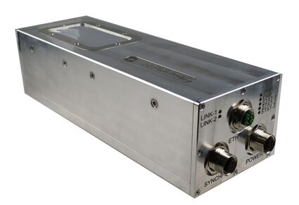
Connector panel LEDs
- There are 2 types of Status LEDs: Network status and Device status.
- Network status LEDs are placed on the left side of the connector board (LINK-1 and LINK-2).
| LINK-1 | LINK-2 | |
|---|---|---|
| 1000Mbps, no activity | Off | On |
| 1000Mbps, activity | Off | Blink |
| 100Mbps, no activity | On | Off |
| 100Mbps, activity | Blink | Off |
| 10Mbps, no activity | On | On |
| 10Mbps, activity | Blink | Blink |
| No link | Off | Off |
- Device status LEDs are placed on the right side of the connector board (PWR, ERR, STAT-1, STAT-2, STAT-3).
Device init
- When proper power supply is connected (POE or adapter), device should power up. It is normal that each LED slightly blink during device's initialization, after some time (1 - 3 seconds) initialization is done and just PWR LED is lit on the right side.
- In case of wrong initialization ERR LED starts to blink (in the number of blinks in one period is coded device's error state, shoot a 5 seconds video for tech support guy). Try to power cycle the device.
Network connection init
- During the Device init process network connection is established. When connection is correctly established LINK-2 LED should irregullary blink (device will not properrly work with other type of link than 1000Mbps!).
- If the Devices status is OK - just PWR LED is lit, but ethernet connection was not correctly established (no LED is lit on left side), you can try to reconnect the ethernet cable without power cycling the device and check the network status LEDs or change your network adapter settings.
Next steps
- If the device init was finished without error and network connection was established, device is ready to start communication with Pixet or to change network settings.
- If the device init was OK, but network connection was not established, it is still possible to change network settings.
Network settings
- Device is by default configured to use with DHCP.
- Other IPv4 methods which device can use are:
- Auto IP (169.254.x.y)
- Static IP (192.168.1.100)
IPv4 method change
- Device must be power cycled before IPv4 method change.
- Attach magnet to the magnetic sensor (magnetic sensor is placed on connector board just under labels STAT-2 and STAT-3), when the magnetic field is recognised, LED STAT-1 is lit. You have just 5 seconds from device's power up to attach the magnet! Otherwise IP address mode change is dissabled to prevent unwanted IP address changes. When dissabled LED STAT-1 blinks fast (power cycle needed).
- Hold the magnet in front of the magnetic sensor for approximately 8 - 10 s, after that, IPv4 method change is enabled, which is indicated with illumination of both STAT-2 and STAT-3 LEDs.
- Movement of the magnet in front of the magnetic sensor leads to the change of the state of STAT-2 and STAT-3 LEDs.
- Each LED state is connected to various IP settings.
- There are 3 IPv4 methods: Auto IP (STAT-3 LED is lit), DHCP (STAT-2 LED is lit) and Static IP (both STAT-2 and STAT-3 LEDs are lit).
- To change the method, just move with magnet until the needed combination of LEDs is achieved. Then move magnet away from magnetic sensor and wait approximately 8 - 10 seconds until both STAT-2 and STAT-3 LEDs start to blink, which means setting the new IPv4 method.
- When LED(s) stop to blink, new IPv4 method is set.
- Power cycle the device.
Pixet communication init
- Do not begin this step, before correctly done steps before! Prerequisites are: blinking LINK-2 LED and still lighting PWR LED.
- Run Pixet, select device in table of found devices.
- The initialization of communication with Pixet is indicated with blinking STAT-3 LED.
- If the init process is done correctly (after about 2-4 seconds), STAT-3 LED is turned off. When STAT-3 LED does not stop blinking or still lights, report the problem.
- Also during the init process, ERR LED can start to blink, if this occurs, shoot a 5s video of the error code for ADVACAM's tech support guy.
- After communication init is done, device is ready to be operated via Pixet.
