WidePix POE v2 Quick Start Guide
Jump to navigation
Jump to search
Prerequisities
- Connect power cable (not needed when using POE)
- Connect ethernet cable
- PC with Pixet
- At least 1Gbit/s ethernet is required
- Magnet
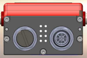
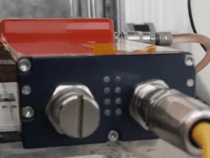
Description of LED indicators
- 4 LEDs Left side
- L1. Device status
- Green blinking 2s - device ready, OK
- Orange still - just init (about 1s)
- Red blinking - overtemperature (> 55˚C) warning
- Red still - fatal error, power cycle the device. If this LED is still red, contact Advacam technical support.
- L2. Error code LED
- Green blinking according to the error (it does not prevent functionality of the device)
- In this case, Technical Support will ask the customer to make 10s video
- L3. Reserved for internal purpose
- Violet still - the device restarted itself (it is not a problem at the device starting, but if this occurs during measurement, it will probably stop working)
- L4. Power supply for the row segment
- Orange still - power on (when pixet is running)
- The LED stays on even when Pixet crashes!
- 4 LEDs Right side
- R1. FPGA
- Orange still - shutter is open
- Orange changes to Red during init
- It is used also during IP reset procedure (described below)
- R2. Device power
- Blue still - power on
- Blue blinks shortly during init
- Blue still and green blinking (result is blue-turquoise) - communication with Pixet during FW revert procedure (described below)
- R3+R4. Eth link (R3 green, R4 red)
- None - no connection
- Only green blinking - 1 Gbit/s, ok
- Only red blinking - lower speed
- Both red and green blinking - lower speed
- Both red and green blinking shortly during init
- Both red and green still - connected to switch, but without access to network
Network settings
IP mode change
- Warning: Static IP adress of the device is reset to the default factory value 192.168.1.100 when this procedure is started!
- Disconnect the device from any network if connected. Connect the device to power.
- After the device init (R1 is Orange, changes to Red and turns off), attach the magnet to magnetic sensor. When the magnetic field is recognized, R1 turns Blue. If R1 starts blinking Blue, you have missed the IP mode change time window (~5 s after power up) and need to start the process over.
- When the change mode is enabled, R1 changes to one of the colors indicating the actual settings (listed below).
- Use magnet for select the preferred settings. There are 3 possibilities of the R1 color for different IP configurations:
- Red = Auto IP
- Green = DHCP
- Yellow = Static IP (= 192.168.1.100)
- Wait for several seconds. R1 blinks several times and turns off. Now the setting is saved.
- Connect the device to the specified network.

