WidePix POE v2 Quick Start Guide: Difference between revisions
Jump to navigation
Jump to search
(Created page with "= Description of LED indicators = thumb 4 LEDs Left side: <br> :L1. '''Device status''' :*<span style="color:green">Green</span> blinking 2s - device ready, OK :*<span style="color:orange">Orange</span> still - just init (about 1s) :*<span style="color:red">Red</span> blinking - overtemperature (> 55˚C) warning :*<span style="color:red">Red</span> still - fatal error, power cycle the device. If this LED is still red, contact Advacam techni...") |
|||
| Line 1: | Line 1: | ||
= Description of LED indicators = | = Description of LED indicators = | ||
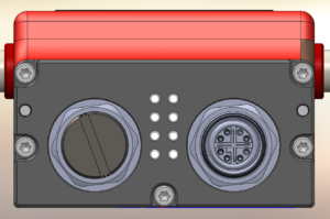
[[File:WPX POE v2 panel.png|thumb]] | [[File:WPX POE v2 panel.png|thumb]] | ||
4 LEDs Left side | |||
=== 4 LEDs Left side === | |||
:L1. '''Device status''' | :L1. '''Device status''' | ||
:*<span style="color:green">Green</span> blinking 2s - device ready, OK | :*<span style="color:green">Green</span> blinking 2s - device ready, OK | ||
| Line 17: | Line 17: | ||
:*The LED stays on even when Pixet crashes! | :*The LED stays on even when Pixet crashes! | ||
4 LEDs Right side | === 4 LEDs Right side === | ||
:R1. '''FPGA''' | :R1. '''FPGA''' | ||
:*<span style="color:orange">Orange</span> still - shutter is open | :*<span style="color:orange">Orange</span> still - shutter is open | ||
Revision as of 11:09, 20 January 2025
Description of LED indicators
4 LEDs Left side
- L1. Device status
- Green blinking 2s - device ready, OK
- Orange still - just init (about 1s)
- Red blinking - overtemperature (> 55˚C) warning
- Red still - fatal error, power cycle the device. If this LED is still red, contact Advacam technical support.
- L2. Error code LED
- Green blinking according to the error (it does not prevent functionality of the device)
- In this case, Technical Support will ask the customer to make 10s video
- L3. Reserved for internal purpose
- Violet still - the device restarted itself (it is not a problem at the device starting, but if this occurs during measurement, it will probably stop working)
- L4. Power supply for the row segment
- Orange still - power on (when pixet is running)
- The LED stays on even when Pixet crashes!
4 LEDs Right side
- R1. FPGA
- Orange still - shutter is open
- Orange changes to Red during init
- It is used also during IP reset procedure (described below)
- R2. Device power
- Blue still - power on
- Blue blinks shortly during init
- Blue still and green blinking (result is blue-turquoise) - communication with Pixet during FW revert procedure (described below)
- R3+R4. Eth link (R3 green, R4 red)
- None - no connection
- Only green blinking - 1 Gbit/s, ok
- Only red blinking - lower speed
- Both red and green blinking - lower speed
- Both red and green blinking shortly during init
- Both red and green still - connected to switch, but without access to network
Network settings
IP address change
- Connect the device to power.
- After the device init (R1 is Orange, changes to Red and turns off), attach the magnet to magnetic sensor. When the magnetic field is recognized, R1 turns Blue.
- When the change mode is enabled, R1 changes to one of the colors indicating the actual settings (listed below).
- Use magnet for select the preferred settings. There are 3 possibilities of the R1 color for different IP configurations:
- Red = Auto IP
- Green = DHCP
- Yellow = Static IP (192.168.1.100)
- Wait for several seconds. R1 blinks several times and turns off. Now the setting is saved.

